

Image quality
Optical imaging quality and modulation transfer function (MTF)

The imaging quality of intraocular lenses (IOLs) is one of the decisive factors in guaranteeing optimal visual acuity in patients following cataract surgery. In order to clarify these dependencies, the key principles and their interrelationships are explained below. The principle limitations of different optical designs are discussed and the aberrations (imaging errors) that occur are shown. Furthermore, typical measurement methods in both ophthalmology (ophthalmology) and product testing (e.g. IOL quality test) are discussed.
A number of different terms are used in the field of optics to describe the optical components of image quality. The most important of these are resolution, contrast, modulation, visual acuity, visual acuity and field of vision. The following chapter explains these terms, their interrelationships and their relevance to ophthalmic optics.
Visual acuity and visual acuity
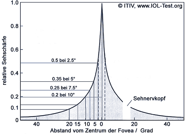
Not all of the terms listed above are relevant to the field of ophthalmology. On the human retina, the density of photoreceptors (" photoreceptors ") and thus also visual acuity decreases rapidly with increasing visual angle (angle between the pixel and the optical center of the retina). The adjacent diagram shows this correlation [Oyster99] [Hecht98].
In addition, the density of receptor cells decreases more with increasing visual angle than the imaging quality of simple optical lenses (e.g. symmetrical lenses with sparse surfaces, which will be discussed later) with increasing field angle. For this reason, when measuring the optical quality of lenses for ophthalmic use, only the central field of vision in the range of approx. +/- 2° of the angle of vision is of importance.
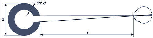
Visual acuity (visual acuity) is usually determined using visual acuity tables based on so-called Landolt rings. The reciprocal value of the narrowest opening in the Landolt ring (measured in minutes of arc = 1/60°) which the patient can still see clearly gives the numerical value of the visual acuity.
On average, people with normal vision can still recognize openings that correspond to an angle of about 1' (one minute of arc = 1/60 degree). This is defined as a visual acuity of 1 or 100%. For example, if a person can only recognize an aperture corresponding to an angle of 2', this results in a visual acuity of 0.5 or 50% (further information can be found in [Oyster99]).
Resolution and modulation
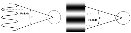
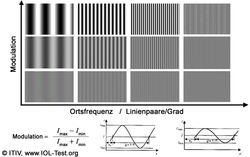
Angular resolution and visual acuity are a measure of more or less the same physical quantity. This also applies to the two terms contrast and modulation. To measure contrast, so-called cosine gratings with different spatial frequencies (number of line pairs per degree or per mm) are used, as shown in the adjacent figure, for example.
As can be seen from the figure above, the ability to recognize the fringe structure obviously depends on two factors:
On the one hand on contrast (or modulation, i.e. the difference between the lightest and darkest areas of the stripe pattern) and on the other hand on the spatial frequency (stripe density) of the cosine grating.
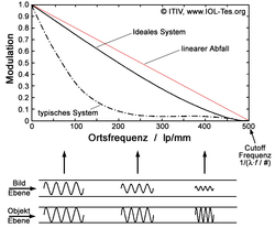
Due to these relationships, the contrast at different spatial frequencies is required to characterize the imaging quality of an optical system (e.g. a lens). For this purpose, for example, different cosine gratings with different spatial frequencies are imaged through the lens one after the other. The contrast achieved is then plotted against the spatial frequency (fringe density) of the different gratings. The graph above shows the resulting visibility curve for an ideal and a typical optical system. It can be clearly seen that even for an ideal system the contrast decreases with increasing spatial frequency. At the so-called cuttoff frequency, the contrast approaches zero. This visibility curve of an optical system is called the modulation transfer function (MTF). MTFs of real optical components and systems are always below the ideal curve.
Point blur function (PSF) and modulation transfer function (MTF)
As the procedure described above for characterizing the imaging quality of an optical system would be extremely time-consuming, a different method of measurement is used instead, which leads to the same result. In the case of an ideal (or perfect) lens, no aberrations occur. The MTF therefore corresponds to the black line in the previous figure.
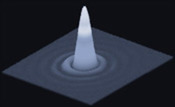
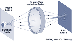
In the normal case of a round aperture (transparent surface of the lens), this curve shows an almost linear progression with a slight belly near the Cuttoff frequency. This is due to diffraction effects caused by the limited optical aperture of the lens [Hecht98]. Due to these diffraction effects, the image of a point light source, which is imaged through a round aperture, shows a concentric ring structure.

These rings are also called Airy rings. Such an image of an ideal point light source is called the point spread function (PSF) of an optical system. The diagram above illustrates the underlying image of a point light source and the resulting ring pattern. Since diffraction is therefore the only remaining limiting factor of the MTF of such an ideal lens, it is also referred to as diffraction-limited.
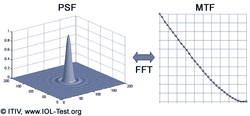
In the 1960s, scientists discovered an astonishingly simple relationship between MTF and PSF: using a simple mathematical function, the well-known Fourier transformation, one representation can easily be converted into the other. Thus, by measuring the PSF using a subsequent two-dimensional Fourier transformation, the MTF can be calculated directly and precisely. Since the availability of high-resolution CCD cameras with a high dynamic range, this significantly faster procedure is therefore often used to determine the image quality of an optical system [ISO11979], [ISO9334], [ISO9335].
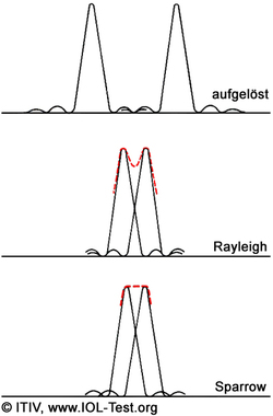
The better the image quality of an optical system, the narrower the central peak of the PSF and the closer the measured/calculated MTF is to the curve of the ideal MTF. The diameter of the first dark Airy ring (from the inside to the outside) of the PSF is also called the spot diameter. This diameter δx can be easily determined using the Fourier transform:
δx = λּ f / D
with the wavelength λ , the focal length f and the diameter of the lens D . The cutoff frequency then simply corresponds to the reciprocal of δx. As can be seen in the diagram above, two neighboring pixels can no longer be perceived separately if their distance is equal to or less than δx (Sparrow criterion).
MTF measurement system

To measure the MTF of IOLs and contact lenses, the Institute of Information Processing Technology (ITIV) has developed an automated measuring stand for measuring image quality in accordance with the international industry standard EN/ISO 11979-2 [ISO11979]. The diagram opposite shows the basic structure of this measuring system based on a HeNe laser with a wavelength of 546 nm as the light source (green light at the maximum sensitivity of the photoreceptors of the human eye [Oyster99]). The pinhole (very small pinhole in the μm range) in conjunction with the colimation lens generates highly parallel laser light. An aperture provides illumination on the surface of the IOL with a diameter of 3 mm (according to ISO).

This laser light is focused by means of an artificial eye, which simulates the cornea and the properties of the anterior chamber of the eye. The IOL to be tested is operated in a water bath in order to operate the IOL in environmental conditions that are as identical as possible to the eye. The image of the focus, which is generated by the artificial eye and the IOL to be tested, is then imaged onto a high-resolution CCD camera with high dynamic range using a diffraction-limited microscope. This image is transferred to a PC, where it is Fourier-transformed and then automatically analyzed. Further information on the MTF measuring stand of the institute can be found under MTF measuring stand .
Contact
Prof. Dr. rer.nat. Wilhelm Stork,
Tel. 0721 / 608 - 42510, wilhelm.stork∂kit.edu